LDO Generator
Low-dropout regulator
This page gives an overview of how the Digital LDO Generator (ldo-gen) works internally in OpenFASoC.
Circuit
This generator is based on convential Digital LDO. The main function of LDO is to maintain constant output voltage which is equal to reference voltage VREF. The comparator is responsible for comparing the two voltage VREF and output voltage (VREG). Based on the comparator output a digital controller takes a decision to turn ON/OFF switches in order to maintain VREG equal to VREF.
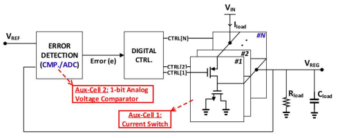
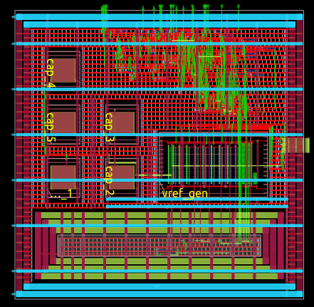
Block diagram of the Digital LDO’s circuit
The Digital LDO consists of the following :
A reference voltage generator (vref_gen)
Comparator, which compares the two voltages
Digital controller, which takes a decision based on comparator output
Array of power switches (PT_unit_CELL)
More information on how the sensor works can be found here.
Generator Flow
To configure circuit specifications, modify the test.json specfile in the generators/ldo-gen/ folder.
To run the default generator, cd into openfasoc/generators/ldo-gen/ and execute the following command:
make sky130hvl_ldo
Note
For other generator options, use make help.
The default circuit’s physical design generation can be divided into three parts:
RTL-to-GDS flow (OpenROAD)
Post-layout verification (DRC and LVS)
‘Simulation’_ (Ngspice & Xyce)
Verilog generation
Running make sky130hvl_ldo (ldo for “digital ldo”) executes the ldo-gen.py script from ldo-gen/tools/. This file takes the input specifications from test.json and outputs Verilog files containing the description of the circuit.
Note
ldo-gen.py calls other modules from ldo-gen/tools/ during execution. For example, configure_workspace.py is in charge of reading test.json, checking for correct user input and choosing the correct circuit elements.
The generator starts from a Verilog template of the ldo circuit, located in ldo-gen/src/. The .v template file have a parameter ARRSZ , which updates according to the specifications.
Example: LDO_CONTROLLER.v line 5 changes the value based on number of switches during Verilog generation.
Note
Currently, the only supported technology in ldo-gen is sky130hvl (hd for “high voltage”).
RTL-to-GDS flow
The “compilation” from the Verilog description to a physical circuit is made using a fork of OpenROAD Flow, which is an RTS-to-GDS flow based on the OpenROAD tool. The fork is in the ldo-gen/flow/ directory.
OpenROAD Flow takes a design from the ldo-gen/flow/design/ directory and runs it through its flow, generating a DEF and a GDS at the end. The design is specified by using the generated Verilog files and a config.mk file that configures OpenROAD Flow to the ldo design.
ldo-gen
├── blocks
└── flow
    └── design
        ├── sky130hvl
        │   └── ldo
        │       ├── config.mk          <--
        │       └── constraint.sdc
        └── src
            └── ldo
                ├── ldoInst.v          <--
                ├── LDO_CONTROLLER.v   <--
For more information on OpenROAD Flow, check their docs.
Note
OpenROAD Flow also creates intermediary files in the ldo-gen/flow/results/ folder, where each file is named according to the step in the flow it was created.
For example, 2_floorplan.odb is the file created after step 2 of OpenROAD Flow Scripts, which is floorplan generation.
The steps from the RTL-to-GDS flow look like this, usual in a digital flow:

Since OpenROAD was developed with digital designs in mind, some features do not natively support analog or mixed-signal designs for now. Hence, in the digital ldo, the physical implementation does not get successfully generated with the original flow.
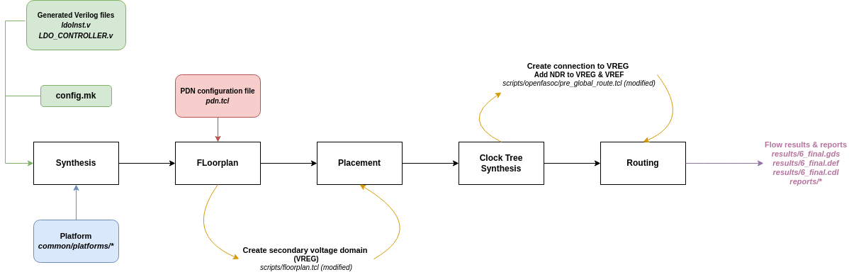
Some changes are then made to customize the OpenROAD Flow repo and generate a working physical design, summarized in the diagram below:
Synthesis
The OpenROAD Flow starts with a flow configuration file (config.mk), the chosen platform (sky130hvl, for example) and the Verilog files generated from the previous part.
From them, synthesis is run using Yosys to find the appropriate circuit implementation from the available cells in the platform.
Floorplan
Then, the floorplan for the physical design is generated with OpenROAD, which requires a description of the power delivery network (in pdn.tcl).
This ldo design implements two voltage domains: one for the VDD that powers most of the circuit, and another for the VREG that is output of the ldo. Such voltage domains are created within the floorplan.tcl script, with the following lines of code:
31# Initialize floorplan using DIE_AREA/CORE_AREA
32# ----------------------------------------------------------------------------
33} else {
34  create_voltage_domain LDO_VREG -area $::env(VREG_AREA)
35
36  initialize_floorplan -die_area $::env(DIE_AREA) \
37                       -core_area $::env(CORE_AREA) \
38                       -site $::env(PLACE_SITE)
39
40   if {[info exist ::env(DOMAIN_INSTS_LIST)]} {
41    source $::env(SCRIPTS_DIR)/openfasoc/read_domain_instances.tcl
42    read_domain_instances LDO_VREG $::env(DOMAIN_INSTS_LIST)
43  }
44}
In the image, line #36 will create a voltage domain named LDO_VREG with area coordinates as defined in config.mk.
Lines #38 to #40 will initialize the floorplan, as default in OpenROAD Flow, from the die area, core area and place site coordinates from config.mk.
And finally, lines #42 to #44 will source read_domain_instances.tcl, a script that assigns the corresponding instances to the LDO_VREG domain group. It gets the wanted instances from the DOMAIN_INSTS_LIST variable, set to ldo_domain_insts.txt in config.mk. This will ensure the cells are placed in the correct voltage domain during the detailed placement phase.
In the image below, notice the two voltage domains (LDO_VREG is the smaller one):
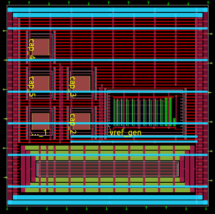
Layout after floorplan (newer versions may differ)
Warning
The ldo_domain_insts.txt file contains all instances to be placed in the LDO_VREG domain . The PT_UNIT_CELL cells are added to ldo_domain_insts.txt and the number of cells changes as per the specifications . Thus, this file actually gets generated during ldo-gen.py.
Placement
Placement takes place after the floorplan is ready and has two phases: global placement and detailed placement. The output of this phase will have all instances placed in their corresponding voltage domain, ready for routing.
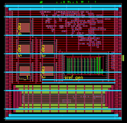
Layout after placement (newer versions may differ)
Routing
Routing is also divided into two phases: global routing and detailed routing. Right before global routing, OpenFASoC calls pre_global_route.tcl:
1# NDR rules
2source $::env(SCRIPTS_DIR)/openfasoc/add_ndr_rules.tcl
3
4# Custom connections
5source $::env(SCRIPTS_DIR)/openfasoc/create_custom_connections.tcl
6if {[info exist ::env(CUSTOM_CONNECTION)]} {
7  create_custom_connections $::env(CUSTOM_CONNECTION)
8}
This script sources two other files: add_ndr_rules.tcl, which adds an NDR rule to the VREG and VREF net to improve routes that connect instances in both voltage domains, and create_custom_connections.tcl, which creates the connection between the VREG net and the PT_UNIT_CELL instances along with comparator and also creates connection between the VREF net and the decoupling capacitors and vref_gen.
Final layout after routing (newer versions may differ)
At the end, OpenROAD Flow will output its logs under flow/reports/, and its results under flow/results/.
Here’s an overview of all changes made from OpenROAD Flow to OpenFASoC’s ldo-gen (the reference directory taken is ldo-gen/flow/):
OpenROAD Flow Scripts configuration |
|
Circuit Verilog description |
|
Power Delivery Network setup |
Create a voltage domain for the output voltage VREG from the PT_UNIT_CELL cells, assigns its instances |
|
Scripts run before global routing to setup the connection between the PT_UNIT_CELL,comparator and the VREG net. |
|
Makefile (modified) |
Set flow directories from the fork, add DRC w/ Magic, add LVS w/ Netgen |
The other files are unchanged from OpenROAD Flow.
Note
For debugging purposes, it’s also possible to generate only part of the flow, visualize the results in OpenROAD GUI or generate DEF files of all intermediary results. For doing so, the Makefile in ldo-gen/flow/ contains special targets.
After running make sky130hvl_ldo in ldo-gen/ once, cd into the flow/ directory and use one of the commands from the following table:
|
Stops the flow after synthesis |
|
Stops the flow after floorplan |
|
Stops the flow after placement |
|
Stops the flow after routing |
|
Runs the whole RTL-to-GDS flow |
|
Opens the design after floorplan in OpenROAD GUI |
|
Opens the design after placement in OpenROAD GUI |
|
Opens the design after routing in OpenROAD GUI |
|
Opens the finished design in OpenROAD GUI |
|
Creates DEF files in flow/results/ of every step in the flow |
|
Prints the value of an env variable recognized by OpenROAD Flow |
Post-layout verification
After generating the design, OpenFASoC runs DRC and LVS to check that the circuit is manufacturable and corresponds to the specified design. In flow/Makefile, the targets magic_drc and netgen_lvs are run using make.
Note
Source files for DRC and LVS are located under common/drc-lvs-check/.
In DRC, Magic takes the generated GDS file and checks for failed constraints. A report is written under ldo-gen/flow/reports/ with any errors found.
In LVS, Magic takes the generated GDS file and extracts its netlist to compare with the original circuit netlist, in order to verify if the physical implementation was done correctly. Files generated from the layout extraction are created under ldo-gen/flow/objects/.
Netgen is then used to run the comparison, outputting a report under ldo-gen/flow/reports/.
Netlists match uniquely.
Circuits match correctly.

Subcircuit pins:
Circuit 1: ldoInst                         |Circuit 2: ldoInst
-------------------------------------------|-------------------------------------------
VREG                                       |VREG
trim2                                      |trim2
trim1                                      |trim1
trim3                                      |trim3
trim10                                     |trim10
trim4                                      |trim4
trim5                                      |trim5
trim6                                      |trim6
trim7                                      |trim7
trim8                                      |trim8
trim9                                      |trim9
mode_sel[0]                                |mode_sel[0]
std_ctrl_in                                |std_ctrl_in
std_pt_in_cnt[4]                           |std_pt_in_cnt[4]
std_pt_in_cnt[5]                           |std_pt_in_cnt[5]
std_pt_in_cnt[7]                           |std_pt_in_cnt[7]
std_pt_in_cnt[6]                           |std_pt_in_cnt[6]
std_pt_in_cnt[8]                           |std_pt_in_cnt[8]
VSS                                        |VSS
cmp_out                                    |cmp_out
ctrl_out[1]                                |ctrl_out[1]
ctrl_out[2]                                |ctrl_out[2]
ctrl_out[0]                                |ctrl_out[0]
ctrl_out[3]                                |ctrl_out[3]
ctrl_out[7]                                |ctrl_out[7]
ctrl_out[4]                                |ctrl_out[4]
ctrl_out[5]                                |ctrl_out[5]
ctrl_out[6]                                |ctrl_out[6]
ctrl_out[8]                                |ctrl_out[8]
std_pt_in_cnt[3]                           |std_pt_in_cnt[3]
mode_sel[1]                                |mode_sel[1]
std_pt_in_cnt[1]                           |std_pt_in_cnt[1]
reset                                      |reset
std_pt_in_cnt[2]                           |std_pt_in_cnt[2]
std_pt_in_cnt[0]                           |std_pt_in_cnt[0]
clk                                        |clk
VDD                                        |VDD
---------------------------------------------------------------------------------------
Cell pin lists are equivalent.
Device classes ldoInst and ldoInst are equivalent.
Circuits match uniquely.
If no mismatch is reported, LVS is successful and the generator ends its job by copying the resulting circuit design files into ldo-gen/work/.
Simulation
The verify the functionality of the design automated simulations are ran using python scripts. The simulations can be run by giving command make sky130hvl_ldo_full in ldo-gen/
The spice template file ldo_tran_ngspice.sp is updated as per the various simulation conditions. Currently the simulations are performed for three different clock frequencies which 0.1MHz, 1MHz and 10MHz. Additionaly , it runs on different output capacitances at VREG.The simulation time is adjusted based upon the clock frequncy and array size. The simulation generates all imporatant variables in raw file which are saved after the simulation is complete.
To better visualize and analyze the simulation results simulations.py incorporates post processing functions which works on raw data that has been generated.Neat and labelled plots are generated for output voltage VREG , VREG ripple , number of switches turned on ,etc. All the plots are saved to ldo-gen/work/output_plots at the end.The data generated by the simulations is also stored in csv files which are saved to ldo-gen/work/csv_data.
Below images are the output plots generated from simulations.
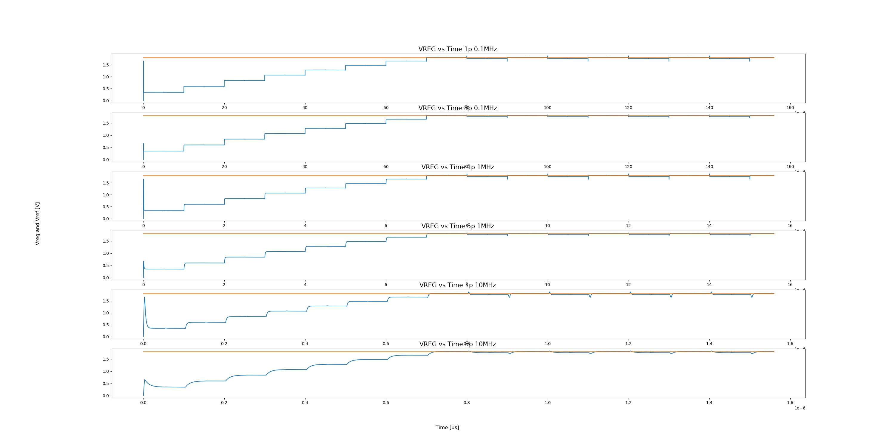
VREG output plot
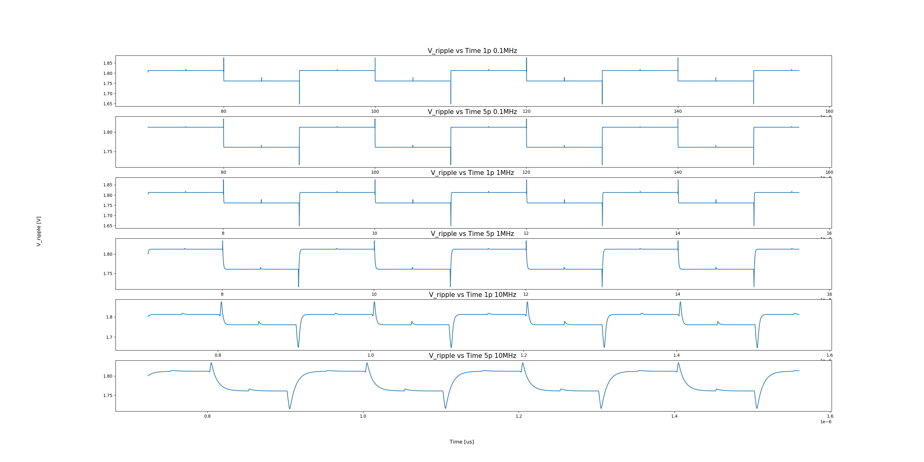
VREG output ripple plot
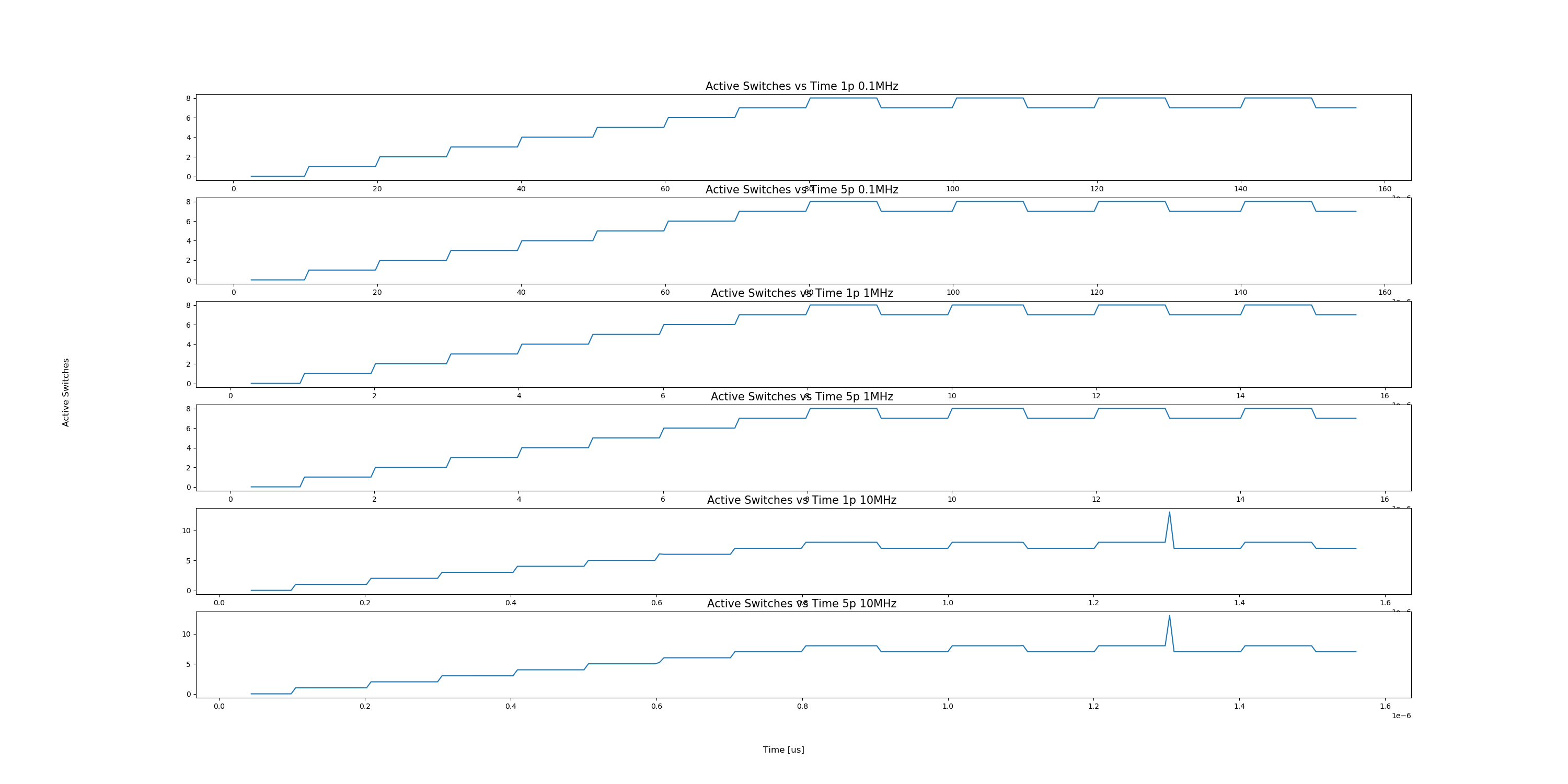
Number of switches turned on (Active Switches) plot
Note
Currently we support Ngspice and Xyce tools for simulations.
If an error is found, the generator may not be working properly. You can file an issue in the GitHub repo to ask for help.
Reference Article
Tutu Ajayi et al., “An Open-source Framework for Autonomous SoC Design with Analog Block Generation,” 2020 IFIP/IEEE 28th International Conference on Very Large Scale Integration (VLSI-SOC), 2020, pp. 141-146.
Last updated: Oct 22, 2025